What is a safety PLC and when should industrial equipment use one?
Quick answer
A safety PLC is a programmable controller designed to monitor safety inputs, execute validated safety logic, and command outputs that move industrial equipment to a defined safe state when a hazardous condition is detected. Typical functions include emergency stops, guard interlocks, light curtains, safe motion control, zone stopping, and restart prevention. A safety PLC does not replace risk assessment, physical guarding, sound electrical design, lockout/tagout, or application validation. It becomes useful when a machine or production line needs multiple safety functions, flexible operating modes, diagnostics, or coordinated stops that would be hard to manage with hardwired safety relays alone.
For more industrial safety control topics, see the safety systems section.
What a safety PLC actually does in a machine safety system
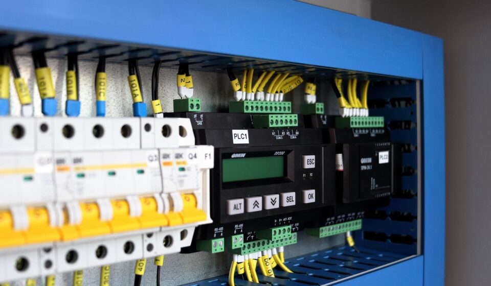
In a functional safety design, a safety function normally has three parts: a sensing element, a logic element, and a final control element. The sensing element may be an emergency stop button, a guard-locking switch, a safety mat, a laser scanner, or a light curtain. The logic element evaluates the state of those devices. The final control element may remove torque from a drive, de-energize a contactor, vent pneumatic energy, close a valve, or command a controlled stop.
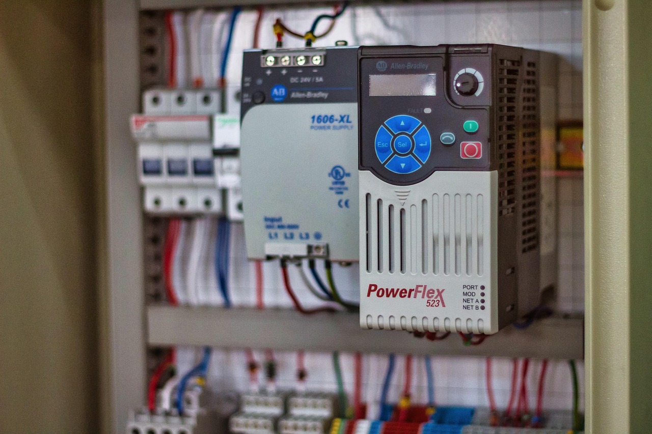
The safety PLC sits in the logic layer. Its role is not to make the entire machine safe by itself. It executes defined safety functions with predictable behavior when inputs change, faults are detected, or a reset is requested. Modern systems often use dedicated safety input modules, safety output modules, certified function blocks, protected project files, diagnostic coverage, and defined fault reaction behavior for safety-related control.
This distinction matters. Many machine safety problems are not caused by a simple lack of logic. They come from unclear operating modes, bypassed devices, poor reset location, uncontrolled stored energy, incomplete validation, or changes made after commissioning. A safety PLC helps only when the surrounding system is designed, tested, and maintained as a safety-related control system.
Safety PLC vs standard PLC
A standard PLC is built mainly for process control, sequencing, productivity, and automation flexibility. A safety PLC is built for safety-related functions that must respond reliably under defined fault conditions. The difference is not limited to the processor. It also includes hardware architecture, firmware, diagnostics, software tools, permissible programming methods, I/O modules, documentation, and validation requirements.
| Comparison point | Standard PLC | Safety PLC |
|---|---|---|
| Main purpose | Controls normal machine operation, production sequence, and process variables. | Executes defined safety functions that reduce risk when hazardous conditions occur. |
| Fault behavior | Fault handling is designed around availability and process control needs. | Fault detection and reaction are designed to move the safety function toward a defined safe state. |
| Input and output devices | Uses general-purpose I/O for sensors, actuators, and machine signals. | Uses safety-rated I/O, monitored channels, diagnostics, and suitable final control elements. |
| Programming approach | Allows broad control logic flexibility. | Often uses certified safety instructions, restricted safety tasks, change protection, and documented validation. |
| Compliance role | May support monitoring and diagnostics but is not automatically acceptable for safety functions. | Can form part of a standards-based safety-related control system when correctly selected, designed, and validated. |
The practical point is straightforward: a safety PLC is not selected because it is more advanced. It is selected because the risk reduction function needs programmable safety control, and the project team is prepared to validate the complete function, not just install certified hardware.
Standards and regulatory context to understand
Safety PLC projects are usually viewed through both functional safety standards and local regulatory obligations. IEC 61508-1:2010 is the broad functional safety reference for electrical, electronic, and programmable electronic safety-related systems. IEC 62061:2021 applies that functional safety approach to machinery safety-related control systems. ISO 13849-1:2023 is widely used for safety-related parts of machine control systems and expresses performance through Performance Levels. IEC 62061 uses Safety Integrity Level language for safety functions. Both approaches require more than a component certificate; they require a defined safety function, a risk-based target, architecture, verification, and validation.
For U.S. workplaces, OSHA requirements and interpretations are especially important because control reliability and machine guarding obligations are legal compliance issues, not just engineering preferences. OSHA lockout/tagout guidance also makes an important distinction: stopping motion through control circuitry is not the same as isolating hazardous energy for servicing and maintenance. A safety PLC may be part of normal safeguarding, but it should not be treated as a substitute for required energy isolation procedures.
For equipment placed on the European market, the EU Machinery Regulation 2023/1230 brings safety control systems and software-related issues, including protection against corruption, into the machinery compliance discussion. In parallel, NIST SP 800-82 Revision 3 frames operational technology security around systems that interact with the physical environment, including PLC-based control. For connected industrial equipment, functional safety and cybersecurity should be coordinated rather than handled as separate afterthoughts.
| Reference | How it is relevant to a safety PLC project |
|---|---|
| IEC 61508 | Provides the generic functional safety framework for E/E/PE safety-related systems. |
| IEC 62061 | Focuses on machinery safety-related control systems and is directly relevant to programmable machine safety functions. |
| ISO 13849-1 | Supports design of safety-related parts of control systems and uses Performance Levels for risk reduction targets. |
| OSHA machine safety and LOTO guidance | Clarifies U.S. workplace obligations, including the limits of relying on control circuitry during servicing. |
| NIST SP 800-82 Rev. 3 | Provides OT security guidance for control systems that monitor or affect the physical process. |
When a safety PLC is the right architecture
A safety PLC is often justified when a machine has multiple zones, several guarded access points, complex mode selection, robot or motion hazards, coordinated conveyors, modular stations, muting logic, or safety functions that must interact with drive control. It can also help where maintenance teams need clearer diagnostics to reduce unnecessary bypassing and improve troubleshooting.
Not every machine needs one. A small machine with one guard door and one emergency stop may be adequately served by a properly selected safety relay or compact safety controller. Choosing a safety PLC for a simple application can add software management, training needs, spare-part complexity, and validation workload without improving actual risk reduction.
A useful selection question is: does the safety requirement need programmable decision-making, zone logic, configurable reset behavior, diagnostics, or communication with other safety devices? If not, a simpler architecture may be easier to validate and maintain. If yes, a safety PLC can make the system more transparent and scalable, provided the engineering process is disciplined. See also: production equipment.
Design and validation checklist
The strongest safety PLC projects begin before hardware selection. Start with a risk assessment that identifies each hazard, each operating mode, and each task: production, setup, cleaning, clearing jams, tool change, maintenance, and troubleshooting. Then define the safety function in plain language. For example: when the loading gate is opened in automatic mode, hazardous motion in zone 2 shall stop and shall not restart until the gate is closed and a manual reset is performed from a safe location.
- Define every safety function before writing logic.
- Determine the required Performance Level or Safety Integrity Level using the chosen standard and risk assessment method.
- Select sensors, logic devices, output devices, and final elements that can achieve the required risk reduction as a complete function.
- Separate standard control logic from safety logic so production changes do not unintentionally alter safety behavior.
- Document reset rules, restart interlocks, mode selection, bypass conditions, muting sequences, and fault reactions.
- Validate the installed system by testing normal operation, foreseeable faults, power loss, restart behavior, and maintenance scenarios.
- Keep records of software versions, parameter changes, test results, and approvals.
Validation is where many weak designs are exposed. It is not enough to confirm that the safety PLC program downloads successfully or that an emergency stop turns on a red indicator. The test should prove that each safety function performs as specified under realistic conditions. That includes the response of the final control elements, not only the logic bit inside the controller.
Cybersecurity and lifecycle management
Connected safety controllers create a lifecycle responsibility. Engineering workstations, remote access tools, backups, firmware, safety network settings, and user permissions all affect the integrity of the safety application. NIST OT security guidance emphasizes that operational technology has performance, reliability, and safety requirements that differ from conventional IT. For a safety PLC, cybersecurity controls should be planned around machine risk, downtime tolerance, and the safety validation process.
Practical measures include role-based access, protected safety programs, controlled remote connections, offline backups, documented change approval, network segmentation, and testing after updates. Patch management should not be ignored, but it also should not be rushed into production without understanding how firmware, device replacement, or software tool changes may affect the validated safety function.
The same lifecycle discipline applies to physical changes. Replacing a light curtain, changing a drive, adding a robot gripper, altering conveyor speed, or modifying a guard can change the assumptions behind the original risk assessment. A safety PLC makes changes easier to implement, but that flexibility becomes a risk if change control is weak.
Common mistakes to avoid
- Treating the emergency stop as the primary safeguard. Emergency stops are important, but they do not replace guarding, presence sensing, safe access design, or energy control.
- Assuming certified hardware makes the application compliant. Certification of a controller or I/O module does not validate the full safety function on a specific machine.
- Allowing undocumented bypasses. Muting, maintenance override, and teach modes must be risk assessed, limited, indicated, and validated.
- Ignoring stored energy. Hydraulic, pneumatic, gravity, thermal, and electrical energy may remain hazardous even after logic commands a stop.
- Mixing production edits with safety edits. Safety software should have stricter access, version control, and approval than ordinary sequence logic.
- Skipping periodic testing. Devices that are rarely demanded can still fail. Periodic inspection and testing should match the risk assessment, standards, and manufacturer instructions.
Frequently asked questions
Does every machine need a safety PLC?
No. Many machines can use safety relays or smaller configurable safety controllers. A safety PLC is most useful when the machine has multiple safety functions, zones, operating modes, diagnostics, or coordinated motion that would be difficult to manage with simple hardwired logic.
Can a standard PLC perform an emergency stop function?
A standard PLC may monitor an emergency stop signal for diagnostics, but using it as the safety logic requires careful standards and regulatory evaluation. In most machinery applications, emergency stop and other safety functions should be implemented through safety-rated devices and validated as part of the safety-related control system.
Is a safety PLC the same as lockout/tagout?
No. A safety PLC can help stop hazardous motion during normal safeguarding, but lockout/tagout is an energy control procedure for servicing and maintenance. Control-circuit stopping should not be confused with isolating, locking, and verifying hazardous energy sources.
How often should a safety PLC system be tested?
Testing should occur before first use, after safety-related changes, after relevant component replacement, and at intervals defined by the risk assessment, applicable standards, manufacturer instructions, and site procedures. The test should verify the complete safety function, including sensors, logic, final control elements, reset behavior, and fault response.
What is the most important document in a safety PLC project?
The safety requirements specification is often the key document. It translates the risk assessment into clear safety functions, target performance, operating modes, reset conditions, response behavior, and validation criteria. Without it, programming and testing can become inconsistent or incomplete.